2009年12月30日 星期三

My blood has whisky

馬上要邁入"twenty ten"了, 回頭看看這一年
失去了不少, 也得到了很多
關於30歲這一年, 我一直在想, Peter Pan他30的時候會不會也跟我
一樣徬徨, 猶豫著結與不結的抉擇, 生氣著台北房子貴的離譜
的現象

就這樣吧, 跟著心走, 隨遇而安

可能是因為要跨年的關係, 加上晚上剛解完的issue
我決定要好好來慰勞一下自己, 所以我就跑去敗了三瓶whisky

為什麼是whisky? 很簡單, 我生下來就是whisky控

左上角的酒, 應該是我目前買的最貴的whisky, Ardbeg, 味道我之前有試過
帶有很濃的泥煤味, 但這種味道則是見人見智, 不是每個人都喜歡
我買的是"almost there"的年份


第二瓶, Highland Park, 老實說, 我沒喝過, 是老闆說值得試試的酒
而且是舊瓶裝, 聽說新瓶跟舊瓶的味道不一樣
那一種好? 我想你應該猜得到

最後一瓶就是我的最愛啦, 目前啦, 余市十五年, Nikka single malt
一想到跨年可以品嘗這些酒, 我身體都熱了起來


2009年12月10日 星期四

Motion Sensor Demo on Beagleboard

If you saw my previous post, it was mentioned my next step is to integrate this 3-axis accelerometer into Android. To prove my implementation could work flawlessly, I ask my colleague, Jeremy to record the following clip.

The demo application is called 3D Level.

The HAL implementation could be found here:
http://gitorious.org/0xdroid/hardware_libhardware

It's based on Michael's porting on Android for Openmoko GTA02.

2009年11月30日 星期一

Build 3-axis Accelerometer on Beagleboard from Scratch

First of all, I would like to thanks Jerry, who is the project manager from STMicroelectronic Taiwan branch. He sponsored 0xlab couple chips of LIS302DL, which is a 3-axis accelerometer device. And Neo (YOSUN's FAE) provides me a fixture for this device. So everything is ready for me to make it work on the Beagleboard.

- LIS302DL
You probably feel it is looked familiar. Yes, this chip is the same motion sensor as Openmoko Freerunner used. The only difference is that its interface would be adopted I2C instead of 3-wire SPI for Beagleboard.

- Power source for LIS302DL
If you probe the schematic of Beagleboard, the expansion header (J3) reserved DC 5v and VIO 1v8 respectively. You can leverage these as the power source for your own devices. Unfortunately, the range of Vdd for LIS302DL is located between 2v16 and 3v6. DC 5v is not fulfilled for this case. So tinker DC 5v is needed. Zerner diode can regulator the voltage as you want. In this case, one reistor and one zerner diode are required.

- TSX0102
It's very Beagleboard specific or you can say it's TI specific. If you want to add an external device on the Beagleboard, a voltage level translator might be necessity. Since most of current devices, the least signaling I/O would be around 2v6. But Beagleboard only provides 1v8 voltage as I/O signaling. The real reason behind this I don't know about it. Maybe for the power consumption issue. Or can I call it's a kind of "product placement"? :p


- Interrupt
Basically, all the I/O to the host controller, Beagleboard, are based on 1v8 signaling. The I2C communication is through TXS0102 to talk between host and device. But there is one more line for one-directional signaling, that is interrupt from LIS302DL to host. My former colleague, Dkay, suggested a simple approach to reslove this. A diode and two pull high resistors would be enough.
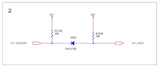
- Kernel driver
The corresponding kernel driver is put here:

http://gitorious.org/0xlab-kernel/kernel

Edit your kernel config with CONFIG_INPUT_ST_MOTION_SENSOR=y.


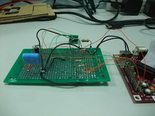
The following picture is the overall picture for this work. Although it's not pretty, but it works perfectly. With evtest utility, I can retrieve input events from LIS302DL device.


# ./evtest /dev/input/event1
Input driver version is 1.0.0
Input device ID: bus 0x18 vendor 0x0 product 0x0 version 0x0
Input device name: "LIS302DL Motion Sensor"
Supported events:
Event type 0 (Sync)
Event type 3 (Absolute)
Event code 0 (X)
Value 3
Min 0
Max 0
Event code 1 (Y)
Value 245
Min 0
Max 0
Event code 2 (Z)
Value 56
Min 0
Max 0
Testing ... (interrupt to exit)
Event: time 12.269714, type 3 (Absolute), code 0 (X), value 4
Event: time 12.269989, type 3 (Absolute), code 1 (Y), value 245
Event: time 12.270233, type 3 (Absolute), code 2 (Z), value 55
Event: time 12.270233, -------------- Report Sync ------------
Event: time 12.273864, type 3 (Absolute), code 0 (X), value 3
Event: time 12.274200, type 3 (Absolute), code 2 (Z), value 56
Event: time 12.274200, -------------- Report Sync ------------
Event: time 12.284332, type 3 (Absolute), code 0 (X), value 4
Event: time 12.284545, type 3 (Absolute), code 1 (Y), value 244
Event: time 12.284698, -------------- Report Sync ------------
Event: time 12.294403, type 3 (Absolute), code 0 (X), value 3
Event: time 12.294799, type 3 (Absolute), code 2 (Z), value 55
Event: time 12.294799, -------------- Report Sync ------------
Event: time 12.304840, type 3 (Absolute), code 1 (Y), value 245
Event: time 12.305023, -------------- Report Sync ------------
Event: time 12.315063, type 3 (Absolute), code 1 (Y), value 244
Event: time 12.315277, type 3 (Absolute), code 2 (Z), value 56


So, what's the next? Making it integrated into Android would be a good idea.

2009年9月21日 星期一

Add omap3 beagleboard support in Qi

My previous post said adding support of beagleboard was the next step in Qi. It seems to be time to release this work. But it's not yet finished. There're couple things on my TODO list. Here is a brief HowTo of building Qi for beagleboard.

- git clone git://git.warmcat.com/qi
- git checkout -b beagle origin/omap3530
- edit CROSS_TUPLE parameter in build script according to your setup
- ./build
- Using the signGP to manipulate qi image. The following is my script to generate bootable image for beagleboard.


#!/bin/sh -x
signGP ./image/qi-omap3530*bin
mv ./image/*.ift MLO


- Make partitions for VFAT and EXT3 respectively in your SD card.
- copy your rootfs into EXT3 partition
- copy MLO file to VFAT partition
- copy your kernel uImage to /boot/ directory and rename it as
uImage-OMAPBEAGLE.bin
- If you have any kernel command needed to add, you can add text file /boot/boot/append-OMAP_BEAGLE
- Boot from SD /* Holding USER key and press RESET key */

If everything goes as well, you can see

Qi Bootloader omap3530 matt-abacus omap3530_146fa25ffad66c65
一 9月 21 19:01:16 CST 2009 Copyright (C) 2009 0xlab.org.


Detected: OMAP3530_BEAGLE, Beagle C3

Trying kernel: SD Card rootfs
Partition: 2 start +819315 512-byte blocks, size 266 MiB
Found: "Linux-2.6.29-omap1-06519-gc3598"
Size: 2089 KiB
Cmdline: console=ttyS2,115200n8 init=/sbin/init loglevel=8 rootfstype=ext3 rootwait root=/dev/mmcblk0p2
Starting --->

Uncompressing Linux.........................................................................done, booting the kernel.
Linux version 2.6.29-omap1-06519-gc3598c9-dirty (matt@matt-abacus) (gcc version 4.2.3 (SQL Star ARM Cross Toolchain 2008-beta1)) #395 Fri Sep 18 14:42:37 CST 2009
CPU: ARMv7 Processor [411fc083] revision 3 (ARMv7), cr=10c5387f
CPU: VIPT nonaliasing data cache, VIPT nonaliasing instruction cache
Machine: OMAP3 Beagle Board
Memory policy: ECC disabled, Data cache writeback
On node 0 totalpages: 65536
free_area_init_node: node 0, pgdat c0432be8, node_mem_map c04af000
Normal zone: 512 pages used for memmap
Normal zone: 0 pages reserved
Normal zone: 65024 pages, LIFO batch:15
OMAP3430 ES3.0
SRAM: Mapped pa 0x40200000 to va 0xd7000000 size: 0x100000
Reserving 12582912 bytes SDRAM for VRAM
Built 1 zonelists in Zone order, mobility grouping on. Total pages: 65024
Kernel command line: console=ttyS2,115200n8 init=/sbin/init loglevel=8 rootfstype=ext3 rootwait root=/dev/mmcblk0p2
..........


Here is my TODO list for reminding,

- Add support for booting from NAND
- Add hardware version detection

PS. Since the DVI module would be only reset one time. So the flash phenomenon on the display device as getting into kernel would not be existed.

2009年9月4日 星期五

Getting start to know ARM-based debug system

It's a VERY VERY late post.

When I was stuck on porting Qi on the beagleboard, the first thought is to use openOCD to see where problem is. Unfortunately, the support for ARM cortex A8 is provided but not full functional. The good thing of opensource is, anything goes wrong or you don't like it, you can just fix by yourself. But the assumption is, you need to know how to fix. So I can't help myself to start to learn the knowledge about ARM debug system. After the co-work with Holger, my ex-colleague, we have some progress to make openOCD work as we expect. He also posted the thing on his blog:

- Standing on the shoulders of giants - Fixing OpenOCD for the Beagleboard

If you are interesting with how to get familiar with ARM-based debug system for Cortex A8, Magnus provides a great introduction:

- Debugging on Cortex-A8, System components

2009年8月18日 星期二

Kill u-boot in the beagle board

If you want to boot up Linux kernel on the beagle board. You need to have two different-phase bootloaders for kernel. The first phase is xloader which take cares CPU, memory, vector table setup stuff. The second one is uboot, it provides interactive commands, verbose booting environment setup, initialization for lots perhiphals of SoC. Of course, it loads the kernel image eventually. But it might not be the best choice for you. Sometimes you just want to get into the kernel, that's it.

I did some dirty hack here:

http://0xlab.org/~matt/kill-uboot-patches/

which against xloader
http://gitorious.org/x-load-omap3/mainline/commit/319b26586fafb86f919f514bcd175838aaab96b3

After applying these patches, you just need to put your xloader(MLO) and your kernel into SD card. Make beagle board boot from SDcard then. You will get a running kernel. But this is still not flexible somehow. Like, you need to edit and re-compile the xloader to change your kernel cmdline. My next plan is to support Qi boot loader in the beagle board.

2009年8月2日 星期日

Dual MMC/SDIO support on Beagle board.

My recent work is to add 2nd MMC/SD support for Beagle board.
The reason is simple, the 1st MMC/SD slot could be used as bootable device, the 2nd one could be the WLAN card interface (SDIO).

To achieve this, you need to tinker your beagle board like the following.

1. Attach the jumper on the location of J3(see schematic).
2. Make a home brew cable to wire up the SDIO interface.

The WLAN module shown on the below picture is GH600 from Azurewave.
Its corresponding GPL-ed driver is available.

http://android.git.kernel.org/?p=platform/system/wlan/broadcom.git;a=summary


In the host side, couple patches could make this work.

http://gitorious.org/0xlab-kernel

Enabling the 2nd MMC/SDIO slot has two approaches. The first one is to wire up the MMC2 slot directly. But the operating voltage of these ports are based on 1v8. Fortunately, the SDIO of this module could be signaling as low as 1v8. In this case,
wiring up to the module directly is much simple.

If the operating voltage of your WLAN module is around 2v6~3v3, transceiver is you plan B. Either designing a level shift circuit or using available voltage level translator could fulfill this requirement. I would suggest using level shift IC such as TXS0108E. TXS0108E is a level shift IC, whcih is designed for the expansion of MMC/SD/SDIO interface particularly.

2009年7月20日 星期一

壓力來自別人還是自己!?

I'm old school man. 對於生活的大事小事, 都是透過朋友及親人的傾聽來宣洩
會想透過blog來紀錄一切, 可能是因為年紀大了, 記不住了

最近嚴重的陷入自我否定的Loop, 雖然明知這種現象是一陣一陣, 也是有一番說詞可以解釋
但就是擋不住自己的失落

可能是因為跟Andy, Werner 共事過吧, 總覺得像是driver development, machine porting
這類的事情應該並不是難事. 而實際上當所有的事情都得自己一步一步做的時候
你會感覺像在山洞行走一般, 永遠不知道什麼時候會有出口

漸漸的, 你會被"懷疑"的心魔給吞噬.

吊詭的是, 沒有人給我壓力. 沒有人告訴我, 你應該要像誰誰誰一樣強
你應該只花幾天就把事情搞定,你應該要送多少patch....諸如此類的.

我不知道我能不能應付這些關卡
我只求我能有勇氣,一步步去發掘自己的無限可能

2009年6月3日 星期三

Hello! 0xlab

I love this team. :)