- LIS302DL
 You probably feel it is looked familiar. Yes, this chip is the same motion sensor as Openmoko Freerunner used. The only difference is that its interface would be adopted I2C instead of 3-wire SPI for Beagleboard.
- Power source for LIS302DL
If you probe the schematic of Beagleboard, the expansion header (J3) reserved DC 5v and VIO 1v8 respectively. You can leverage these as the power source for your own devices. Unfortunately, the range of Vdd for LIS302DL is located between 2v16 and 3v6. DC 5v is not fulfilled for this case. So tinker DC 5v is needed. Zerner diode can regulator the voltage as you want. In this case, one reistor and one zerner diode are required.
- TSX0102
 It's very Beagleboard specific or you can say it's TI specific. If you want to add an external device on the Beagleboard, a voltage level translator might be necessity. Since most of current devices, the least signaling I/O would be around 2v6. But Beagleboard only provides 1v8 voltage as I/O signaling. The real reason behind this I don't know about it. Maybe for the power consumption issue. Or can I call it's a kind of "product placement"? :p
- Interrupt
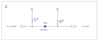
Basically, all the I/O to the host controller, Beagleboard, are based on 1v8 signaling. The I2C communication is through TXS0102 to talk between host and device. But there is one more line for one-directional signaling, that is interrupt from LIS302DL to host. My former colleague, Dkay, suggested a simple approach to reslove this. A diode and two pull high resistors would be enough
 .
.- Kernel driver
The corresponding kernel driver is put here:
http://gitorious.org/0xlab-kernel/kernel
Edit your kernel config with CONFIG_INPUT_ST_MOTION_SENSOR=y.
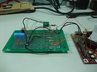
The following picture is the overall picture for this work. Although it's not pretty, but it works perfectly. With evtest utility, I can retrieve input events from LIS302DL device.

# ./evtest /dev/input/event1
Input driver version is 1.0.0
Input device ID: bus 0x18 vendor 0x0 product 0x0 version 0x0
Input device name: "LIS302DL Motion Sensor"
Supported events:
Event type 0 (Sync)
Event type 3 (Absolute)
Event code 0 (X)
Value      3
Min        0
Max        0
Event code 1 (Y)
Value    245
Min        0
Max        0
Event code 2 (Z)
Value     56
Min        0
Max        0
Testing ... (interrupt to exit)
Event: time 12.269714, type 3 (Absolute), code 0 (X), value 4
Event: time 12.269989, type 3 (Absolute), code 1 (Y), value 245
Event: time 12.270233, type 3 (Absolute), code 2 (Z), value 55
Event: time 12.270233, -------------- Report Sync ------------
Event: time 12.273864, type 3 (Absolute), code 0 (X), value 3
Event: time 12.274200, type 3 (Absolute), code 2 (Z), value 56
Event: time 12.274200, -------------- Report Sync ------------
Event: time 12.284332, type 3 (Absolute), code 0 (X), value 4
Event: time 12.284545, type 3 (Absolute), code 1 (Y), value 244
Event: time 12.284698, -------------- Report Sync ------------
Event: time 12.294403, type 3 (Absolute), code 0 (X), value 3
Event: time 12.294799, type 3 (Absolute), code 2 (Z), value 55
Event: time 12.294799, -------------- Report Sync ------------
Event: time 12.304840, type 3 (Absolute), code 1 (Y), value 245
Event: time 12.305023, -------------- Report Sync ------------
Event: time 12.315063, type 3 (Absolute), code 1 (Y), value 244
Event: time 12.315277, type 3 (Absolute), code 2 (Z), value 56
So, what's the next? Making it integrated into Android would be a good idea.

沒有留言:
張貼留言